
In the late 1800s and early 1900s ASME code was created to govern the fabrication of pressure retaining equipment due to explosions that were frequently occurring around the US. ASME Section VIII Division 1 guides the design principles for pressure vessels and boilers. The code is formulas and rules based utilizing industry experience to guide the design thicknesses of your vessels. In other words, Division 1 takes into account what we’ve learned over the years when vessels have failed and creates rules to make sure it doesn’t happen again, this leads to conservative design rules.
ASME Section VIII Division 1
- 3.5 based on the Ultimate tensile strength (UTS).
- 1.5 based on specified minimum yield strength (SMYS)
- Rules for design pressure under 3000psig
ASME Section VIII Division 2
In contrast ASME Section VIII Division 2 is a design by analysis code. The formulas and rules are based on stress analysis instead of industry experience. This allows for much less design margin utilizing the rules below:
- 2.4 based on UTS
- 1.5 based on SMYS
- Lowest of the two
How does this help? As material gets stronger, yield gets closer to tensile. As yield gets closer to tensile you can use the 2.4 of UTS which is advantageous for design.
Why is the allowed? The safety factor can be lower because a stress analysis is required. The division 2 code can be used for design pressures from 15psig to 10,000psig. Anything higher you’d be using Division 3. And in reality, anything below ~1,000psig won’t see a larger enough advantage in thickness to justify the additional testing.
Example Stresses and Calculations – 72” ID @ 3000 psig
Div. 1
Div 1 w/ SA-516-70 (38/70) (UTS/SMYS)
S= 20,000psi
t- 5.93”
Div. 2
w/516-70
S=25,300psig
T= 4.53”
Stress Analysis
In order to utilize the higher allowable stresses, the code requires a stress analysis of each portion of the vessel per Part 4 and Part 5 of the code. Part 4 of Div 2 provides the rules-based stress analysis required. For complex shapes, Part 5 is used for design by analysis
For a div 2 vessel it’s up to the manufacturer to determine if it should be designed to part 4 or part 5. Part 4 and part 5 are component based. So sometimes you can use part 5 for a complex nozzle on what would otherwise be a fairly standard vessel.
Class 1 vs Class 2
In 2017 changes presented a new option in Div 2. In essence, the new section was a way to allow more manfacturers to ‘test’ out Division 2 without having to hire a PE to see if it would work for their business. As such, class 1 is still a little more conservative than class 2.
Class 1 – “Div 2 lite”
Class 2 – “true div 2” as we know it
Class 1
Design margin 3.0 on UTS
No use of Part 5 to override Part 4 rules
No PE Stamp required as long as fatigue is not a design condition (for UDS or manufacturer’s design report)
Class 2
Design margin 2.4 on UTS
Use of full Div 2 code
PE stamp required
How does TFES take advantage of the code?
We look for high yield/tensile ratio. Where the yield encroaches on the tensile strength you will see the most benefit in your allowable stresses. Examples, find plate with 50ksi/70ksi or 60ksi/85ksi. Materials with these stresses will save significant money over standard SA516-70 plate. It should be noted, as materials become stronger, code will limit certain plate thicknesses.
User Design Specification
- All Division 2 vessels require a User Design Specification.
- The user has to provide the UDS. The user must specify the code edition and the class.
- In a perfect world the end user would provide a UDS for the bid – perfect world
- The UDS specifies the conditions and exposure of the future equipment for the site it will ultimately be installed.
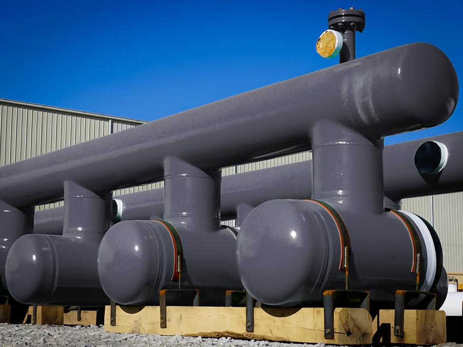
So you’re on a budget? Check out these 5 tips to save money on your next Slug Catcher Project.
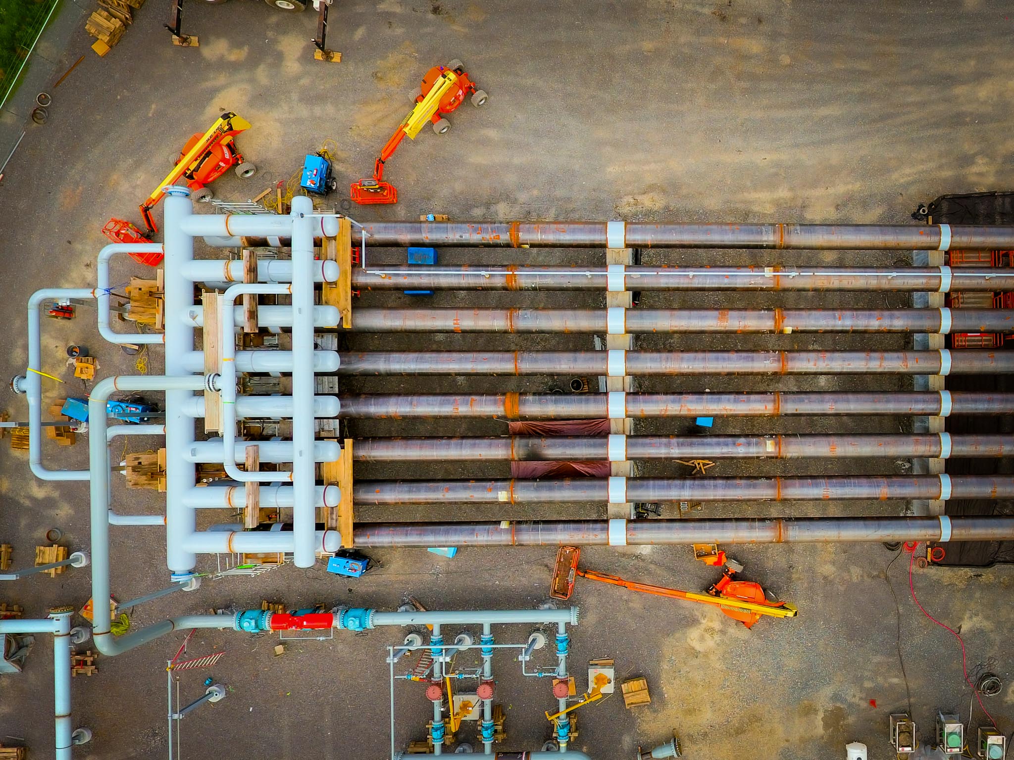
As a leader in Slug Catcher design, here are some guidelines every engineer should know.
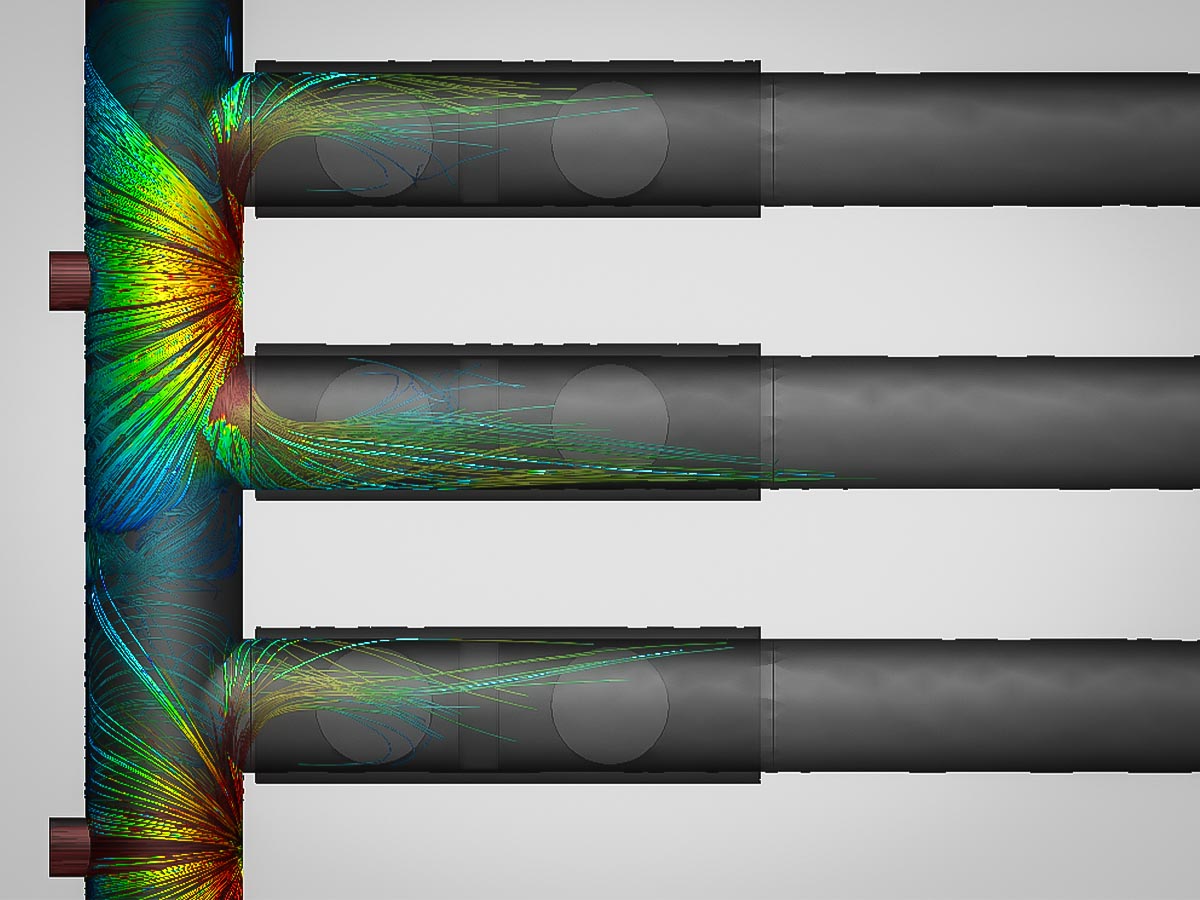
Understanding the separation methods for your finger-type slug catcher.
WHY US
Taylor Forge Engineered Systems
has continued the reputation of traditionally dependable products
to a variety of industries.
Integrity
We don’t compromise our practices and we won’t cut corners.